How to Draw Internal Threads in Autocad 2d
- Download source - 39.21 KB
- Download demo - 23.31 KB
Problem and Solution
Software development in industry, building and many other fields requires working with CAD drawings. The most popular CAD formats are AutoCAD DWG and AutoCAD DXF, the latter being "simplified" dwg - a special format to be used by developers. The problem is that DXF and DWG formats are really complicated. They have dozens of objects with hundreds of interaction tricks and thousands of properties. Official DXF Reference from Autodesk has 256 pages though it fails to describe many important facts. Hence, the development for CAD drawings is often required but is not easy to implement. This article is to tell you how to write the DXF reader in C#, what problems can arise and of course you can find example in C# source code, which is free for use under MPL license.
DXF Structure
DXF is an open ASCII format from Autodesk and you can easily find documentation on it in the web. Here are some words about it. Below is a very simple example, to show the main parts:
0 SECTION 2 ENTITIES 0 LINE 10 39.19953392043317 20 36.4554281665769 30 0.0 11 39.19953392043322 21 736.4554281665768 31 0.0 0 ENDSEC 0 EOF
0 - introduction of extended symbol names, following the "0"
SECTION, ENDSEC - begin / end of section. Sections can include Header, Entities, Objects. In the above code, you see only Entities section where the entities are.
LINE - begins LINE entity description. Lines:
10 39.19953392043317
mean X1 double value. The value after 20 is Y1, after 30 - Z1 (0 in 2D drawings). 11, 21 and 31 codes are consequently for X2, Y2, Z2. So here we see the line with coordinates (39.19.., 36, 45.. - 39,19.., 736,45..) - this is vertical line.
So our aim is to read this ASCII format. We need to load the file to stream and to take lines - even lines (0, 2, 4..) are CODE, odd lines (1, 3, 5...) are VALUE and repeat this procedure step by step till the end of file "EOF".
public void Next() { FCode = Convert.ToInt32(FStream.ReadLine()); FValue = FStream.ReadLine(); } public DXFEntity CreateEntity() { DXFEntity E; switch (FValue) { case " ENDSEC": return null; case " ENDBLK": return null; case " ENDTAB": return null; case " LINE": E = new DXFLine(); break; case " SECTION": E = new DXFSection(); break; case " BLOCK": E = new DXFBlock(); break; case " INSERT": E = new DXFInsert(); break; case " TABLE": E = new DXFTable(); break; case " CIRCLE": E = new DXFCircle(); break; case " LAYER": E = new DXFLayer(); break; case " TEXT": E = new DXFText(); break; case " MTEXT": E = new DXFMText(); break; case " ARC": E = new DXFArc(); break; case " ELLIPSE": E = new DXFEllipse(); break; default: E = new DXFEntity(); break; } E.Converter = this; return E; }
The method to read properties of entities is essentially similar to the one described above but it has one important point: different entities have both identical and different properties. For instance, many Entities have "base point" - in DXF, which is described by codes: 10 (x), 20 (y), 30(z):
LINE 10 39.19953392043317 20 36.4554281665769 30 0.0
These codes are the same for LINE, CIRCLE, ELLIPSE, TEXT and for many others. So we can make Object-Oriented structure to read and to store the properties in order to avoid double-coding. We will store Layer and Base Point in entity "DXFVisibleEntity" which will be ancestor for all visible entities. Look at the code to read these properties:
public class DXFVisibleEntity : DXFEntity { public DXFImport.SFPoint Point1 = new SFPoint(); public override void ReadProperty() { switch (Converter.FCode) { case 8: layer = Converter.LayerByName(Converter.FValue); break; case 10: Point1.X = Convert.ToSingle(Converter.FValue, Converter.N); break; case 20: Point1.Y = Convert.ToSingle(Converter.FValue, Converter.N); break; case 62: FColor = CADImage.IntToColor(Convert.ToInt32(Converter.FValue, Converter.N)); break; } } }
We use the same approach to read the second coordinate in LINE, radius in Circle and so on.
DXF File and DXF Import .NET Structure

This scheme shows main parts of DXF file and the way they are connected with the C# source code in the project. The dash lines stand for associations between DXF file objects and objects, programmed in C#.
CADImage is a class for loading from DXF file and drawing to Graphics. It stores the DXF Entities in field:
public DXFSection FEntities; In the scheme, it is DXFSection.
DXFEntity is base class for all Entities classes. Classes DXFBlocks and DXFSection are not visible. Class DXFVisibleEntity is the ancestor for all visible Entities.
By the way, the scheme above is made in DXF format:) in ABViewer software.
CAD Tricks
If you are not familiar with AutoCAD, please pay attention to the structure of DXF entities. There is a special entity "Block" which may have many "inserts" in the CAD drawing. Block is just set of entities (including nested blocks) which can be inserted many times.
Note
Block changes many properties of element when showing it. So if you want to know the color of entity, it is not enough to read "Entity.Color" - it is necessary to see all the Inserts and Blocks, in which this entity can be included. To get the correct color in DXF Import .NET project we made the following function: EntColor(DXFEntity E, DXFInsert Ins).
Please use EntColor() function get the correct Color type even if you do not have Blocks in the file. Pay attention that the most common color is "ByLayer" and in order to read the correct color, we need to read the color from Layer entity. This functionality is also provided in this function.
Below is the EntColor function. It has many tricks, for instance checking the layer.name == "0" - in DXF layer "0" is special and elements with color "ByLayer" get the color from Block if they are on "0" layer.
public static Color EntColor(DXFEntity E, DXFInsert Ins) { DXFInsert vIns = Ins; DXFEntity Ent = E; Color Result = DXFConst.clNone; if(Ent is DXFVisibleEntity) Result = E.FColor; if(E.layer == null) return Result; if((Result == clByLayer)||(Result == clByBlock)) { if((vIns == null)||((Result == clByLayer)&&(Ent.layer.name != " 0"))) { if(Result == clByLayer) { if(Ent.layer.color != clNone) Result = Ent.layer.color; else Result = Color.Black; } } else { while(vIns != null) { Result = vIns.color; if((Result != clByBlock) && !((Result == clByLayer) && (vIns.layer.name == " 0"))) { if(Result == clByLayer) Result = vIns.layer.color; break; } if((vIns.owner == null)&&(Result == clByLayer)) Result = vIns.layer.color; vIns = vIns.owner; } } } if((Result == clByLayer)||(Result == clByBlock)) Result = clNone; return Result; }
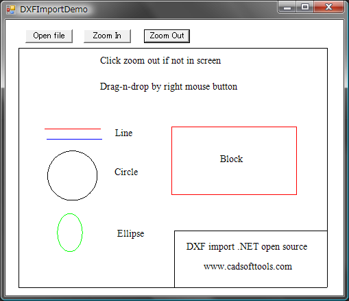
How to Use the Software
The main code is in DXFImport.cs. You can just use this file in your project or see to it as an example of reading and visualization of DXF files.
Sample code to use DXFImport.cs is Form1.cs.
How to View Entities
In Form1.cs, we use the Form1_Paint event:
private void Form1_Paint(object sender, System.Windows.Forms.PaintEventArgs e) { if (FCADImage == null) return; FCADImage.Draw(e.Graphics); }
We can use FCADImage.Draw() for drawing to any Graphics - for instance, to printer. FCADImage.Draw() function should use a special algorithm, when each entity is drawn with the use of block/insert/layer parameters.
public void Draw(Graphics e) { if (FMain == null) return; FGraphics = e; FEntities.Iterate(new CADEntityProc(DrawEntity), FParams); }
Pay attention to FEntities.Iterate() func, it allows accessing all entities including their being inside the blocks. This is how it works: There is a class DXFGroup which is an ancestor of Entity and which can store array of Entities. For instance, Block is ancestor of DXFGroup and can store many entities like LINE. For better unification, we can use ONE BASE GROUP ENTITY object for all the drawing, this Entity will have array of all entities, each of them can also be the Group - the classic "Tree".
Iterate method finally should call Draw() for each Entity in order to draw it to the Graphics:
protected static void DrawEntity(DXFEntity Ent) { Ent.Draw(FGraphics); }
Draw() method is overridden in descendants of Entity to draw particular entities. Let us see in detail how it is implemented in DXFLine:
public override void Draw(System.Drawing.Graphics G) { SFPoint P1, P2; Color RealColor = DXFConst.EntColor(this, Converter.FParams.Insert); P1 = Converter.GetPoint(Point1); P2 = Converter.GetPoint(Point2); if (FVisible) G.DrawLine(new Pen(RealColor, 1), P1.X, P1.Y, P2.X, P2.Y); }
- We get the Real Color via
DXFConst.EntColor(this, Converter.FParams.Insert);as I described before. - Points are converted from Global Coordinates to screen coordinates in function
GetPoint().GetPointnot only converts global-to-screen but also usesBlockoffsets and block scale inside. Thus it facilitates the development work, eliminating the need to "see" what block is being drawn at the moment - Block changes "FParams.matrix" to draw itself. And all entities coordinates use this "FParams.matrix". - Entity is drawn to the given
Graphics G:
So you can draw to printer, to raster image or to other Graphics.
DXF Import .NET Reference
public class DXFConst
Stores constants and base functions.
public class DXFMatrix
Class to work with coordinates.
public struct FRect
Description of 3D space where the CAD drawing is situated in global coordinates.
public struct CADIterate
Stores all needed parameters for entities when processing "Iterate" function.
public class CADImage
Class to draw CAD drawing.
public class DXFEntity
Base class for all DXF Entities.
public class DXFGroup : DXFEntity
Base class for all group entities.
public class DXFTable : DXFGroup
Class to read from DXF "Table" section - here it reads only Layers.
public class DXFVisibleEntity : DXFEntity
Base class for all visible entities (invisible - are "DXFTable", "DXFLayer", etc.)
public class DXFCustomVertex: DXFVisibleEntity
Special class for 3D point in DXF.
public class DXFText: DXFCustomVertex
Stores and Draws "Text" DXF entity.
The following classes are for particular DXF entities:
public class DXFLine : DXFVisibleEntity public class DXFArc: DXFCircle public class DXFEllipse: DXFArc public class DXFLayer: DXFEntity
public class DXFBlock : DXFGroup
Class to work with DXF Block.
public class DXFInsert : DXFVisibleEntity
Class to work with "Insert" in DXF, for AutoCAD users this is "Block reference". Blocks are not visible, Inserts are visible.
Conclusion
The purpose of the article is to give some advice how to write DXF readers. DXF file structure is not so difficult as its logical presentation. The article looks through the base DXF format problems and shows how to find solution for them. The example source is written in C# and may be helpful for all who need to have access to DXF files.
Other Projects on The Code Project
On The Code Project, you can already find another DXF reader:
- http://www.codeproject.com/KB/cs/dxfreader.aspx
The main advantages of our project as compared to the project above are:
- Block / Inserts
- Layers
- Text
which are not presented in that DXF reader.
History
This is the first open source version of DXF Import .NET.
Source: https://www.codeproject.com/Articles/156522/DXF-Import-NET-Read-and-View-AutoCAD-Format-Files
0 Response to "How to Draw Internal Threads in Autocad 2d"
Post a Comment